Export filter invocation
The filter can be ivoked the same way as other filters: File → Export → vrml
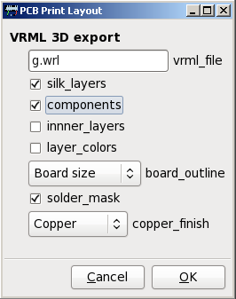
Following options are available:
- vrml_file – name of output file, where the the model will be stored. The file will contain complete model, there are no external references to models or textures (unless some custom model contains them)
- silk_layers – the model will contain all silk layers.
- components – the model will be populated with components, if they exist in the library
- inner_layers – the model will contain also inner layers. If left unchecked, only top and bottom layers are exported
- layer_colors – if checked, the layers colors (as defined in PCB) are used to differentiate the layers, including separate color for selected entities. Useful feature when you want to examine one or more separate tracks.
- board_outline – specifies how the board outline (laminate substrate) is created. You can choose:
- No Outline – no board is displayed, all tracks and components fly in the free air; use this option to see connections in inner layers
- Outline Layer – The board shape is created from standard Outline layer. Only straight lines are taken into account (polygons and components are ignored); line segments are connected together to form board outline. This option does not provide very good results for boards with openings.
- Shape Layer – polygons from special layer called Shape are used to create board online. Lines, arcs and components are ignored. When this option is used, the solder mask is simulated by color change of copper and laminate (to avoid color change on overlapping semi-transparent polygons)
- Board Size – the board has rectangular shape, size is specified in board properties
- solder_mask – the board is covered with semi-transparent solder mask. The mask do not contains openings for pins and pads, it can be used just to improve the look of assembled board. In case the board outline is created using Shape layer, the mask is simulated by color change of copper and laminate
- copper_finish – type of the finish; all copper is covered by the finish material, including inner layers:
- Copper – bare copper, no finish
- Gold plated – gold plated board
- HAL – tin plated board
The components on the board
Board can be populated by components. The library containing 3D models of components has to be prepared and the proper models has to be assigned to the footprints. The component models can be standard VRML files which can be included into final 3D model, or scripts used to generate the VRML model on-fly.
To keep current PCB application untouched we decided to use special files as the additions to footprint files. These files contain mapping between the component footprint placed on the board and its 3D model, together with variable definitions which can be used to customize the model. We call these files component map files.
Additionally, each project can contain additional map used to override definitions from component map files. We call it project map file.
The concept of map files and on-fly generated models gives the output filter high flexibility; one model can be used by several footprints, one parametrized script can be used to create hundreds of parts. With relatively small amount of models and/or scripts we can cover thousands of components.
Component models
Component models contain 3D models of the components. Details are described on separate page.
Component models are located in the vrml subdirectory of the PCB’s data directory <path_to_pcb_binary>/../share/pcb/vrml. It contains following subdirectory structure
- models – static VRML models of components
- scripts – scripts used to generate VRML models on-fly. It also contains scripts to calculate variable values.
- fpgen – footprint generator scripts; these scripts are not used by VRML export, they are used to create footprints compatible with models; these scripts are part of the provided model library
These directories are base directories – there can be any subdirectory structure under them. The path to model or script in the map file should then contain the path relative to the base directory.
Component map files
Component map files act as the glue between footprint and its 3D model. They contain the model location (or name of script used to generate it on fly), its transformation (move, scale, rotate) and variable definitions used for model parametrization.
Component map files are stored in the footprint library together with footprints. Because PCB does not keep the location of the footprint file, we have to use alternate method to locate the footprint file and its corresponding map file:
- the footprint name (without .fp extension) has to be stored in “Description” field of the component; it is stored there automatically, when footprint is loaded from library
- the footprint file is located by traversing the directory structures with footprint libraries (the procedure from PCB library browser is used to locate correct footprint in case of duplicities; in fact, stolen piece of code is used)
- the map file is named <footprint_name>.3dm or <footprint_name>.fp.3dm and it is stored at the same location as the footprint file
Map file format
Map file contains variable definitions. Variable definitions are specified as name-value pairs, one pair per line. Value is separated from name by combination of whitespaces and /or colon or equal sign.
There are predefined variables: model, alt_model, translate, rotate, scale, overlay, alt_overlay, overlay_translate, overlay_rotate and overlay_scale. These variables have special purpose and they should not appear in the model. They have specific behavior and they control the creation and the placement of the 3D model on the board.
Remaining variables are user-defined variables. Their value is used to expand variables in model during VRML export. Value of variable can be static text or output of script. Scripts are identified by @ used as first letter of value. If the value starts with @, rest of value is used as command (with parameters) and first line of script output is used as variable value. The content of component’s “Value” description field is attached as last parameter to the command. This allows to create component descriptions based on component value for example.
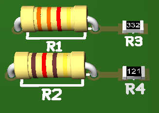
Here are some definitions, taken from axial resistor model:
STRIPE_COLOR1: @val-rt3.pl 1
STRIPE_COLOR2: @val-rt3.pl 2
STRIPE_COLOR3: @val-rt3.pl 3
STRIPE_COLOR4: 1 0.85 0.24 shininess 1
On first three lines, the value is generated by script val-rt3.pl called with first parameter representing stripe number and contents of “Value” field appended as second parameter. The result is the color code. The last line contains the static color value (gold color).
Map file can be divided to sections. In future we plan to use single map file for more 3D output filters with incompatible format and the sections are the way how to differentiate output formats.
Section is identified by section name, surrounded by square brackets. All variable definitions following the section name belongs to this section, until different section name is found. Section names are predefined and their names are case sensitive. Unknown sections are ignored (but they can be recognized by another output filter). Following sections are implemented for VRML export filter:
[common]section is common for all output formats[vrml]section contains variables specific for VRML format
If no section is defined at beginning of map file, the [common] section is used as default.
Empty lines and lines starting with # (comments) are ignored.
Project map files
Project map file allows to override values from component map files and/or define new variables. Project map file is located in the project directory (where the layout file is stored) and its name is derived from layout name – .pcb extension is replaced by .3dm.
The format is similar to component map file, including sections and on-fly generated values. The only difference is that each name-value pair is preceded by reference designator. For example:
R1: STRIPE_COLOR1: @val-rt3.pl 1
R1: STRIPE_COLOR2: @val-rt3.pl 2
R1: STRIPE_COLOR3: @val-rt3.pl 3
R1: STRIPE_COLOR4: 1 0.85 0.24 shininess 1
Typical usage of project map file is to change IC description or visual adjustments of individual components (color, position).
The variables defined in project map file have precedence over the variables defined in component map files. It applies to predefined variables and for user-defined variables as well.
How the map file is used
When export filter processes component it first tries to locate the footprint file and corresponding map file. If any of these files is missing, the component is not exported.
The model variable is used to identify the model. It can be static file (located in <pcb_datadir>/vrml/models directory) or script (identified by @ as its first letter and located in <pcb_datadir>/vrml/scripts directory). If the model file does not exist (or script execution fails), export filter tries to use alternate model, identified by variable alt_model. Alternate model can be also static file or script.
If the primary or alternate model is found, it is copied to output file. Variables are replaced by their respective values, conditional parts are processed accordingly. The model is adjusted using predefined variables translate, rotate and scale before it is placed on the board.
Predefined variables translate, rotate and scale can be uses to re-use existing models for new parts, for example scale down the 0805 resistor to get 0402 one. But such practice should be avoided; it is better to create new model for it or use clever script to generate the model on-fly.
Finally, the model is placed on the board. Its position is determined by position of center mark in footprint, which is aligned with Z axis of the model. The angle is determined by angle between zero mark and first pad/pin of component placed on board and position of first pad/pin in the footprint file (that’s the reason, why we have to find proper footprint file in the library). In current implementation if first pin is located on center mark, the angle calculation fails and angle is set to be 0.
Just to remind – all mentioned variable values are taken from project map at first place, and if they are not found there, they are taken from component map file. We can perform some artificial effects (like lift the component off the board) without touching component map files.
The overlay model is secondary model placed over the primary model. It is identified by variable overlay (and its fallback alt_overlay) and its transformations overlay_translate, overlay_rotate and overlay_scale. The overlay model is processed the same way as the primary model.
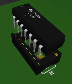
The intended use of the overlay model is to combine two components in one, for example to combine IC with socket to get IC in socket or to add cooler to power transistor without necessity to create new model for “IC in socket” or “Transistor with cooler”. In current implementation the export does not distinguish between primary model and overlay when processing variables from project map file – both models have the same reference designator. For example the image on right side was created using following lines in the project map file:
U1: translate: 0 0 10
U1: overlay: @dipsocket.pl ...